
Start with the groove width, not the tool you already have
The fastest way to create trouble is to choose a cutter or grooving insert first and only then try to make the groove fit it. Start with the drawing, confirm the groove width, depth and corner form, then check whether the job calls for a straight wall, a radius at the bottom or a relief on one side. If the part is going into a hydraulic system, seal land or retaining feature, that last detail matters more than most operators think.
On turning jobs, make sure the insert width gives you enough side clearance for chip flow, but not so much that the groove needs unnecessary spring passes. On milling, confirm the cutter diameter against any shoulder or nearby feature. A groove that looks generous on screen can be tight once you allow for tool nose radius, holder clearance and the real machine travel on the day.
Keep chip control in mind before the tool starts cutting
Grooving creates short, hot chips that can weld to the insert if the cut is too dry, too slow or too deep for the material. Stainless, medium carbon steels and aluminium all behave differently, so the same feeds and speeds will not always give the same result. In humid coastal areas like Durban, coolant condition and concentration become even more important because poor coolant breaks down faster and chip wash away is not as forgiving.
- Use enough coolant pressure to clear the groove, not just wet the insert.
- Break the cut into sensible depths if the groove is deep or narrow.
- Check chip evacuation on the first part, then again after a few minutes of cycle time.
- Watch for recutting chips in blind grooves, especially on long runs.
If the machine is near a load-shedding affected area, build in a restart routine that lets the operator inspect the groove before continuing. A half-cut groove with packed chips can ruin the next pass within seconds.
Use entry moves that protect the edge of the groove
A lot of insert damage starts right at entry. If the tool plunges straight into full width at speed, the edge of the insert takes a knock before the cut is stable. A short lead-in, a controlled ramp, or a small entry offset can make a big difference, especially on harder materials and interrupted cuts. That is true on both turning centres and milling machines.
Where the machine and toolpath allow it, start the groove with a lighter cut and then step into full depth. This reduces shock and gives the chip a path out of the cut. It also helps on older machines where axis response is not perfect and servo lag can leave a slight mark at the start point.
- Keep entry moves short and predictable.
- Avoid sudden changes in feed right at the first contact point.
- Leave room for the tool holder so it does not rub the shoulder.
- On deep grooves, plan a clear retract path before the insert packs up.
Set the insert height and centreline properly
Grooving tools are unforgiving when the insert is too high or too low. Even a small height error can change chip formation, increase burrs and make one side of the groove carry more load than the other. On lathe work, check centre height with a proper gauge and do not trust a visual guess. On mill grooving, make sure the cutter axis is square and that the workholding is not lifting the part under load.
If the tool is mounted off-centre, the insert can rub instead of cut, which shows up as heat, noise and a rough finish. That is often mistaken for a bad insert when the real issue is setup. A quick check with a test pass on scrap material can save a lot of wasted inserts and frustration later in the shift.
Program for the real machine, not the clean simulation
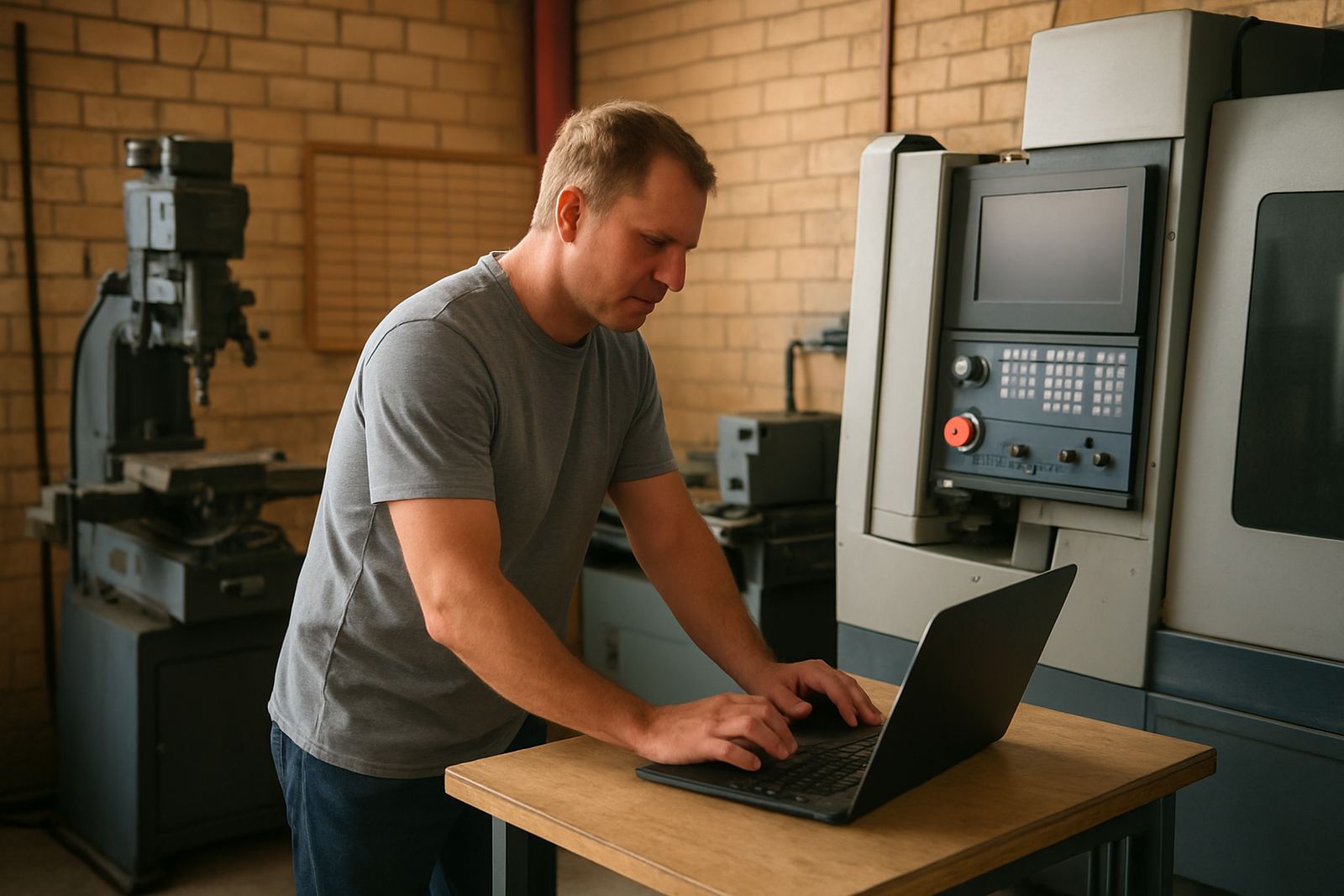
Good groove programming has to suit the machine as much as the drawing. Backlash, acceleration limits, servo tuning and spindle condition all affect how the tool behaves under load. A perfect toolpath still needs a practical feed rate, a safe retract and a finish allowance that matches the machine on the shop floor.
On multiaxis or live-tool setups, watch for accidental clashes between the holder, subspindle or turret and the workholding. A groove that is simple in theory can become awkward if the machine needs to index through a tight space. If the job is going to multiple machines, keep the post-processor and setup notes aligned so the same groove is not programmed two different ways by two different programmers.
- Use the machine’s actual acceleration limits when setting feed changes.
- Check every retract for turret, chuck and fixture clearance.
- Keep a standard grooving template for common materials and widths.
- Record the final successful settings so the next run starts faster.
Use first-off parts to tune, then lock the process down
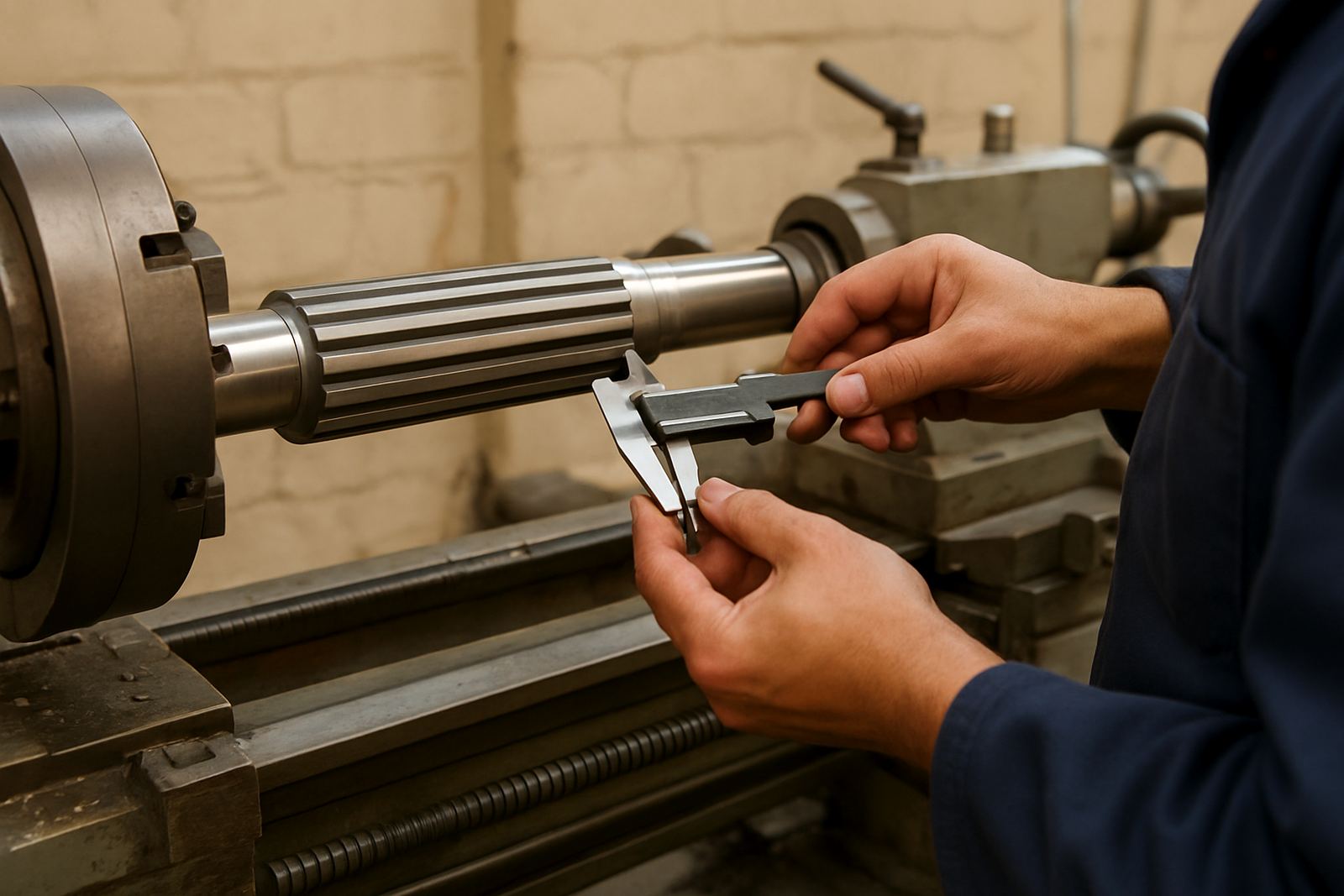
The first good groove should not be the end of the setup. Measure width, depth, finish and burr formation, then look at the insert under magnification if the finish is not consistent. Small changes in feed or coolant direction can improve edge quality quickly. That is often the difference between a part that passes and a part that needs hand work.
One Johannesburg job we saw on a mild steel shaft kept chipping the groove edge on the second pass. The issue was not the insert grade, it was a slightly oversize programmed width combined with chip build-up on the retract. After a small adjustment to the path and a cleaner coolant wash, the job settled down and the insert life improved enough for the shop to finish the batch without interruptions. Once a groove is stable, save the settings, label the holder and make the setup repeatable for the next order.
Build a grooving standard that survives busy weeks
Grooving often gets rushed because it looks like a small operation, but the costs add up fast when inserts fail or parts need rework. Shops that do better usually have a simple standard: the groove drawing is checked, the tool is confirmed, the first-off is measured and the programme notes are stored where the next operator can find them. That is especially helpful when shifts change or when owner-operators have to step in during busy periods.
If your shop runs multiple machines, it also helps to keep one person responsible for post tuning and another for the practical setup notes. That way the programmer, setter and operator are not working from three different versions of the truth. A clear process saves time, reduces scrap and makes grooving far less painful when deadlines get tight.
How to reduce insert trouble on the next grooving batch
The main lesson is simple: most grooving problems start before the insert touches the material. Good width checks, better chip control, correct centre height and realistic feed moves do more for quality than chasing a miracle insert grade. When those basics are right, the groove is cleaner, the cycle is steadier and the shop spends less time stopping to fix a small problem that grew into a bigger one.
For shops in Pretoria, Centurion, Vereeniging, Durban, Cape Town and the wider Gauteng area, the same rule applies, but the local conditions change how it is carried out. Coastal humidity, power interruptions and mixed machine ages all affect the final result. Get the setup right once and the groove job becomes a repeatable part of production, not a surprise every time the order comes in.